So you want to build a train game huh? With trains and tracks and pathfinding. But the question is, how do you model all this stuff in code?
You might be thinking, “oh, easy, that’s going to be a graph structure: nodes and edges. Then I can do <insert graph pathfinding algorithm here> to pathfind. Easy! Done!” Yes, but also, no. It’s much much deeper and more complicated than that.
Let’s dive in.
Version 1: Graph with Nodes and Edges
Imagine we had track layout like so:
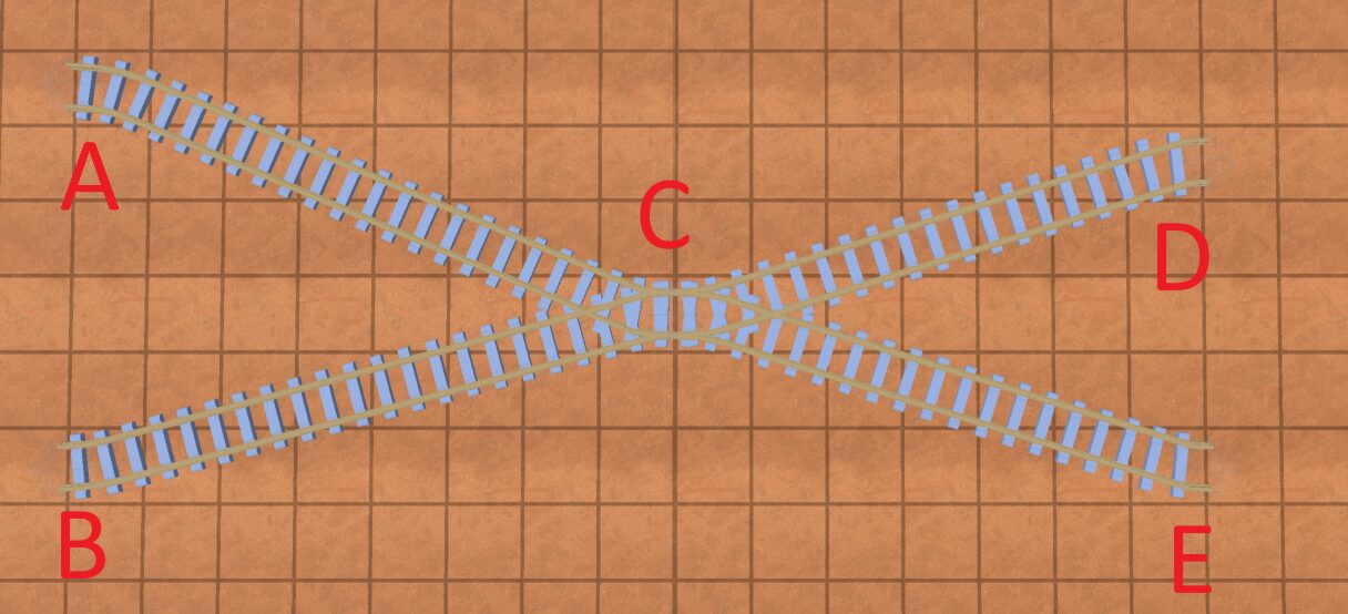
So initially we model the graph with nodes and edges. The “nodes” are junctions, and the “edges” are the tracks between the junctions. And here is a strict definition of junction:
Junction: where multiple tracks meet, or the end of a track
So you can see in the above photo we have 5 junctions.
So, modeling the above image with edges/nodes would look like this:
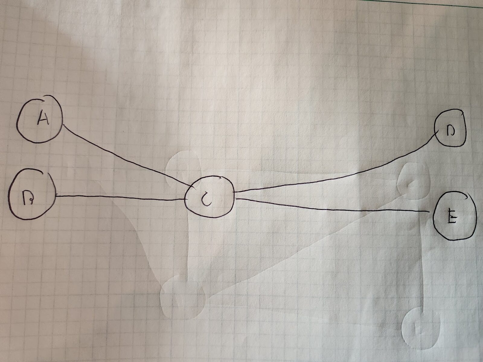
A,B,C,D, and E are track “junctions”, and the lines between them are track.
Okay, this is a good starting point. However, there’s a problem: when trains enter a node, they can’t exit ANY track connected to that node. Take node/junction C for example. If a train approaches node C from node B, it then can’t go on the track to node A. That’d require a “sharp turn” that just doesn’t make sense. It could if it went down the track to node D or E, but we’re trying to model forward moving paths only(for now). So what do we do?
Version 2: Add Track Connection Direction
Let’s look at a slightly simpler track:
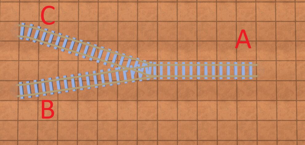
To solve the “sharp turn” problem, we can realize something: all “junctions” essentially have one of two directions that tracks connect in. And trains can cross from tracks that connect in one direction to tracks that connect in another.
So in our above pictures, trains can go from:
A -> C
A -> B
B -> A
C -> A
In terms of modelling a junction in code, essentially, you want a direction “1” and direction “2”. They should be 180 degrees from each other. In my game, I modeled them like this:
class Junction:
	var _angle: float
	var _opposite_angle: float
	var lines: Array[TrackConnection]

class TrackConnection:
	var track: Track
	var approach_from_angle: bool
So when we add a track to a “junction” we determine which of our two sides it connects from.
Great! So we’re ready to do some pathfinding on our track now right?
Right?
Not quite. We still need to model the graph. So how do we do this?
Version 3: Modeling junctions
Well, what if we had an internal “node” for each track, and connected the nodes together for tracks that can be traversed? We’d arrive at something like this:
The problem here is, there’s nothing stopping a train from going from, say, node C -> Node A -> Node B, even though going from track C to B shouldn’t be possible at this junction. So, we need to add a directed graph for all our tracks.
What that will look like:
- Every track will have 2 edges: one in each direction between junctions
- Every track that connects to a junction will have 2 “internal” nodes in that junction: an “in” node if the edge connecting to the junction points to the junction, and an “out” node if the edge connecting to the junction is pointing away from the junction.
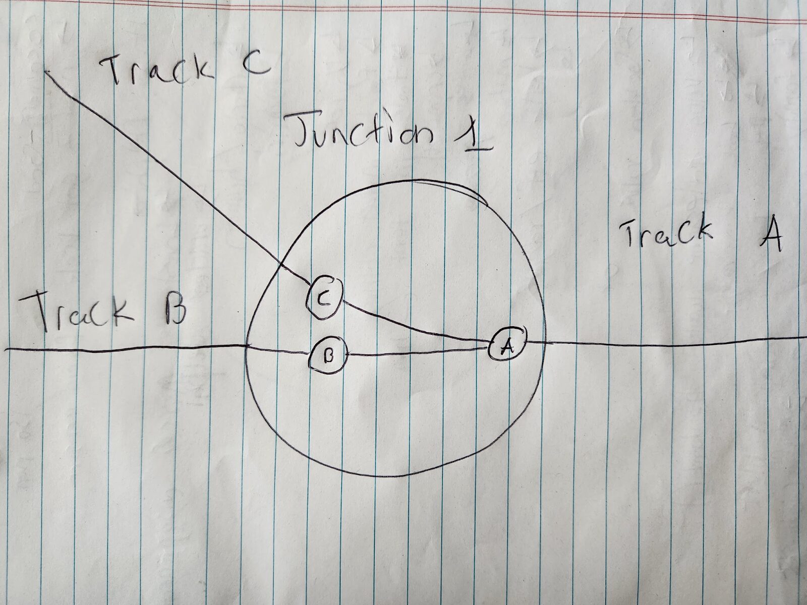
So it’ll look something like this:
A, B, and C are different tracks heading into a junction. The large circle in the junction. The circles inside the large circle are internal connection nodes.
Whew! That’s awfully complicated for 3 little lines meeting together, but you can see how we got here.
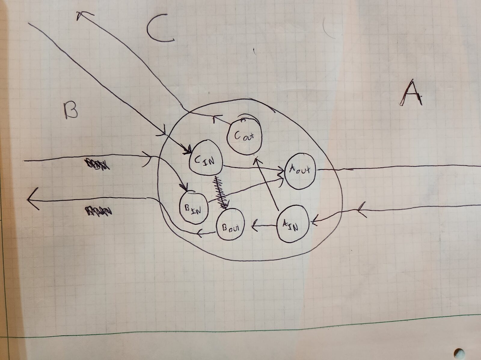
Now, if you’re coming in on say track C, and want to go to track A, the traversal would look like this:
Cin -> Aout
You could also go from track B to A via this:
Bin -> Aout
However, you cannot go from track C to track B, because there is no connection from Cin to Bout(well there was, but I erased it because it was wrong 😛). So you can see how this internal, directed structure shows you how you can traverse across junctions.
Note that essentially you have 2 “disconnected” directed graphs: one for forward movement on a series track, and one for backwards movement on a series of tracks. They are connected if you have a track that loops back on itself, like so:
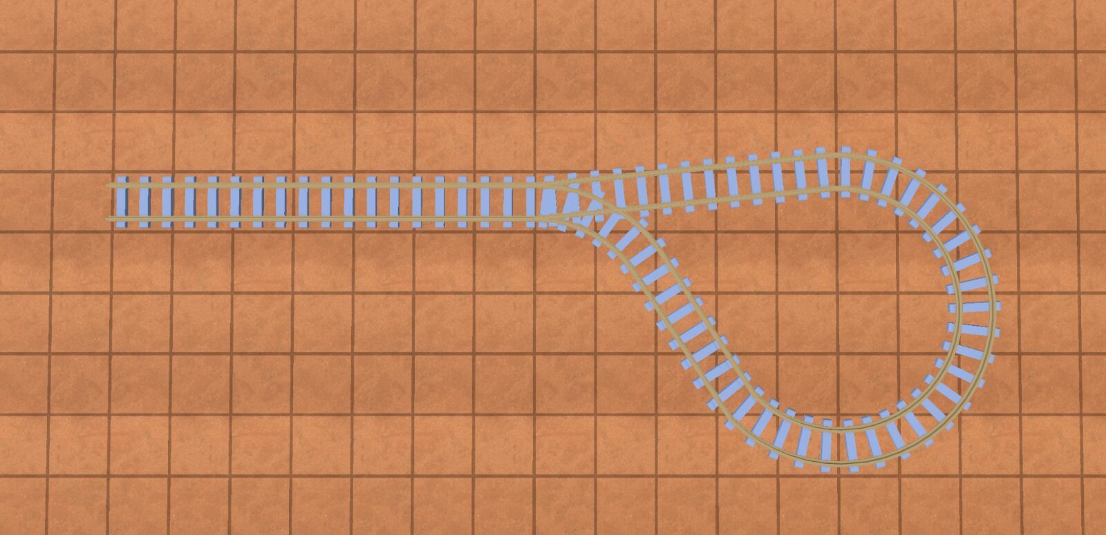
They can also be connected if a train is able to reverse(detailed in “modeling reversing trains”).
Here’s another example that models a track between two junctions:
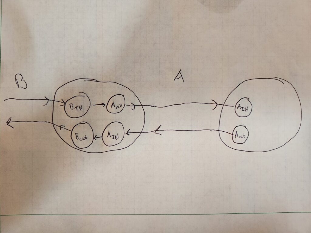
“B” and “A” are tracks, the two large circles are junctions between the tracks.
Great! So now our graph is set up for pathfinding. If we want to go from any track through a junction to any other track in that junction, we have a directed graph that models these directions.
Keeping track of the “ends” of a track
The other thing we need to keep track of is which “end”(start or end) of the track is connected at a junction. That is, one end of the track will be 0 length, and the other will be the track total length(say 100 units). This data isn’t necessary for conducting pathfinding along the track, but once we have a path, it’s necessary to know where to place our train along the track as it’s moving across.
So combining all the above, the code for the node might look like this:
class JunctionNode
	var name: String
	var junction: Junction
	var track: Track
        var connected_at_start_of_track: bool # Whether the start of the end of the track is connected to this junction
        var is_out_node: bool # Whether this node is an “in” or an “out” node
In terms of naming, I named my nodes like follows:
<junction_name>-<track_name>-<in/out>
Some examples:
junction_1-track_a-in
junction_1-track_b-out
This is really helpful when debugging your graph.
Okay, now trains probably need to “stop” at stations and other things. Trains also reverse right? Oh man, that sounds complicated. How do we model that? Let’s start with stops first.
Version 4: Modeling stops
For a train game, a train might stop somewhere in the middle of a track that might correspond to a train station, for example. To model this, we simply add a node in between two junctions in the direction of travel for the train. Keep in mind though: trains have length(they are not infinitesimally small), so the front of the train will stop somewhere different than the back of the train.
Let’s start with the simple, but incorrect model first. Imagine if we just modeled a stop as a point. Depending on which direction the train is travelling to that stop, it will be placed differently on a track. In the image below, the blue boxes are possible train positions, and the red circle a stop:
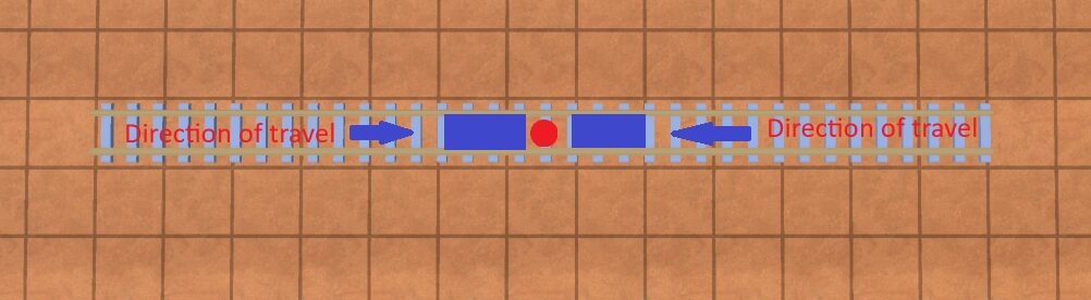
BAD example of a stop
You can see that where the train will actually stop is ambiguous. This is problematic if you expect the train to stop at a specific place along a track, for example to take cargo “off” the train into a station.
To solve this, we model a stop as 2 points: the “front” of the stop and the “back” of the stop. What part is the front or back of the stop doesn’t matter, just that you keep track of them. It should look like so:
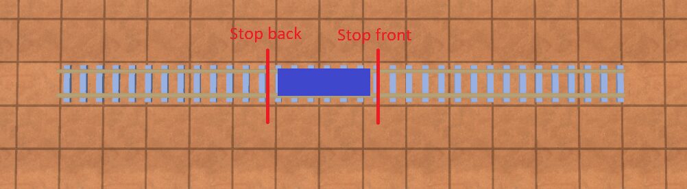
Now, depending on the direction of travel along the track, we can tell the front of the train to stop at “stop front” or “stop back”.
In this example, whenever the train is travelling from left to right along the track, we want the “front” of the train to stop at “stop front”. If it’s travelling from right to left, we want the front of the train to stop at “stop back”.
Great, so how do we model this in our graph? Take a look at “Stop F” and “Stop B” in the below diagram. There’s a lot going on but focus on those first:
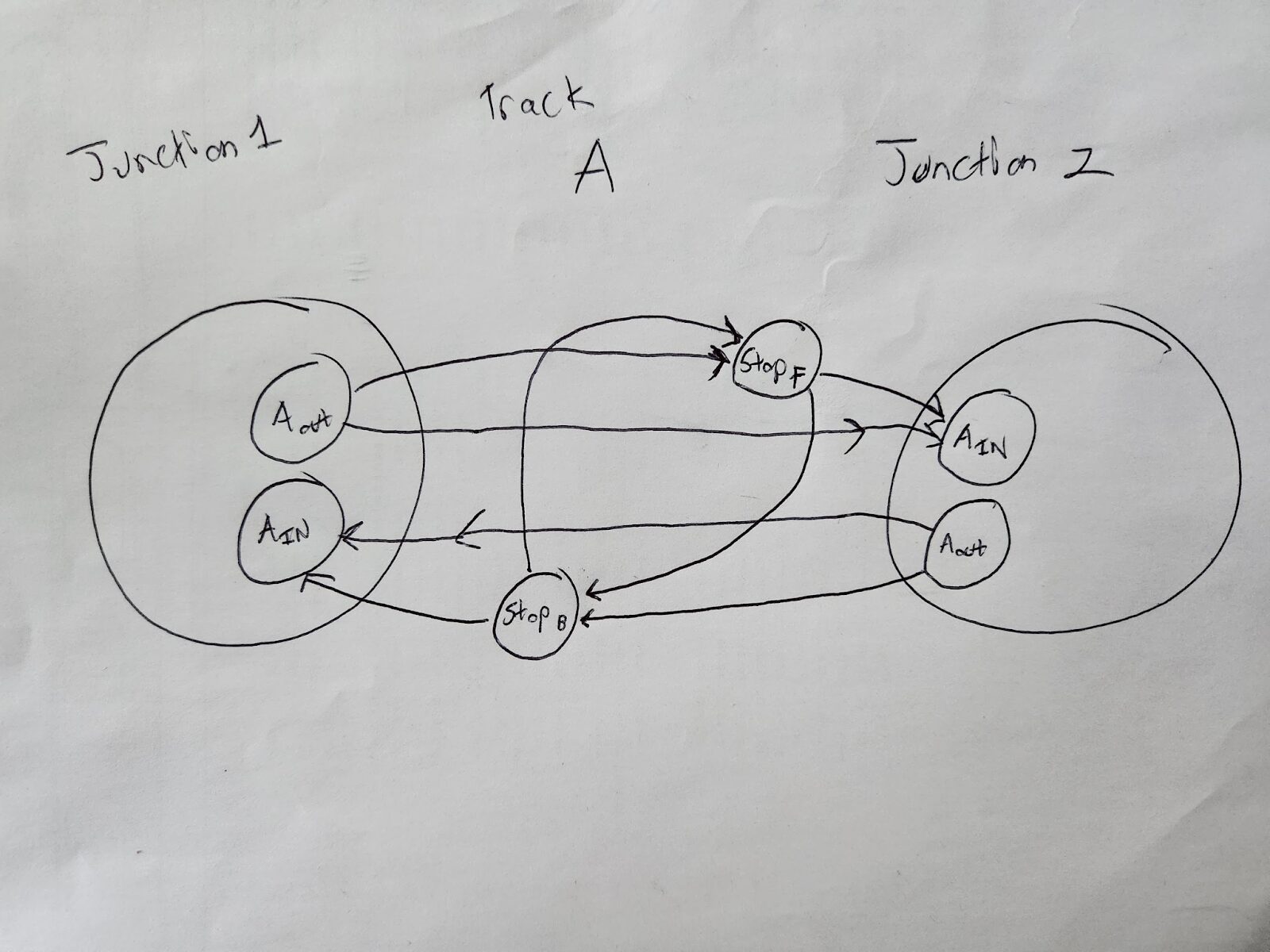
Essentially, we add an extra connection between Aout and Ain for each direction: StopF(for forward) and StopB(for backwards). Note that the stops look “offset” from each other in the image: that’s intentional. Stops will be associated with a position along the track. This position will be different for the “stop front” and “stop back”; they need to be offset so that the “center” of the train always sits in between the center of the “stop front” and “stop back”, regardless of which direction the train is approaching the stop. We can do this by finding the center and then offsetting. Again, this “offset” doesn’t matter for pathfinding or building your graph, but when you have your train moving along the path, it’ll matter for where exactly on the track it stops.
For example:
Imagine a track in 100 units long
A train is 10 units long
You want to place a stop centered at position 75 along the track
So the “back stop” would be at 70 units and and the “front stop” would be at 80
The code would look something like this:
class StopNode
	var name: String
	var track: Track
	var track_pos: float # position along the track from the front of the track
	var train: Train # The train this stop is for
BONUS: Design Choice
There’s a design choice I made in my game, that you may want to make in your game as well. Train stops must be at least a train-length away from junction nodes.
Imagine we had a train like the blue objects below, and the red lines indicated the front and back of the stop:
You can see that the train crosses this junction. Because of this, it would require that in order to get to the stop, it has to take a specific path. For example, if the train was approaching the junction from track B->A, it would not be able to properly stop at the stop, since the “end” of the train would be hanging through the intersection on track B. However, when using a pathfinding algorithm such a A*, you can only specify a start and end node, not a “path”.
You can get around this by first pathfinding to the “back” of the stop, and then the “front” of the stop. There would also be some considerations on how to “select” which track the stop would be on when placing the stop, as well as modeling stations that can “bend” to the track.
Here’s a great time when you can put on your PM hat:
Is this added complexity worth the squeeze? Will the user really want to place stations that cross junctions?
For me, for the hobbyist game I was making, the answer was “no”, so I opted to not implement cross-junction stops, and instead impose the above limitation(“no stops across junction”) in my code/game.
Version 5: Modeling Reversing Trains
Let’s start with some vocabulary:
schedule: a series of stops a train goes through in a loop; eg: Stop A, Stop B, Stop C, back to stop A
Okay, so we have trains that go forwards. But in my game(and from what I see most train games), I want trains to be able to reverse if the trains have engines on both ends. So how do we model that?
In reality, a train can reverse anywhere on a track. But modelling that is complicated: Suddenly, our track is no longer a series of decision points at junctions/stops, but now the train can reverse….at any point on the track? The most obvious brute-force method is that you could model that as a bunch of discrete nodes at set intervals along that track that connect to each other, but that would absolutely EXPLODE the graph complexity. Maybe there’s some other modelling choices you could make, but often in engineering when you’re butting up against a difficult problem, it helps to stop thinking of how to solve the problem, and instead reframe/reask the problem:
“When would a train need to reverse”?
And honestly, there’s only 2 viable answers I came up with:
- At a stop, when it needs to turn around to get to it’s next stop
- At a junction, if it needs to go from one track to another track at the junction that are on the same side
All other reverse scenarios don’t really make sense, so we don’t need to model them(reversing in the middle of a track). I will address #1 here and address #2 in a later section.
#1 is pretty simple to address: simply connect the train’s “stop front” to it’s “stop back” in the graph. I assume in my game(and other games), that trains will be standing still at their “stops”; therefore, once they reach a stop, they will be able to reverse direction.
So take a look at this image again:
We simply connect stopF and stopB via a directed edge to allow reversing. Now, when we are pathfinding between stops in a schedule, we know we can “reverse” the train at a specific stop by simply traversing the edge that connects the front and back of a specific stop.The position of the “back” of the train will now become the position of the “front” of the train. Then the train can go in the other direction.
So how does this work with pathfinding?
Version 6: Pathfinding
Let’s give a naming convention to a stop:
Stop_<stop name>_<forward/backward>
So we might have Stop_A_Forward, Stop_A_Backward, Stop_B_Foward, Stop_B_Backward, ect
When navigating between Stop_A and Stop_B, if a train can reverse, we don’t care if the train navigates to a stop’s forward or backwards node, just as long as it gets there. So when navigating from Stop_A to Stop_B we could do:
Stop_A_forward -> Stop_B_backward
Stop_A_forward -> Stop_B_forward
Stop_A_backward -> Stop_B_backward
Stop_A_backward -> Stop_A_forward
This means we have to run pathfinding 4 times between each pair of nodes. This means that if you have n stops, the pathfinding algorithm will run 4n times. If a train can’t reverse, then we always use the “forward” nodes of a stop. This will run in just n time.
For pathfinding, use whatever algorithm you fancy. I use the A* algorithm(https://en.wikipedia.org/wiki/A*_search_algorithm).
In this algorithm, the edges will be the tracks, the “cost” will be the length of the track(unless it’s a reversal edge, see below), and the nodes will be StopNodes or JunctionNodes as described above.
Simply create your graph using the models outlined above, plug it into an A* algorithm, and viola, you have your models for a train, how to pathfind between spots, and when you want to show “progress” of where your train is on a path, your models will have the data to reconstruct the path fully!
If you want to stop here, you have a pretty good idea of how to model tracks for your train game. If you want more “advanced” functionality, keep on reading!
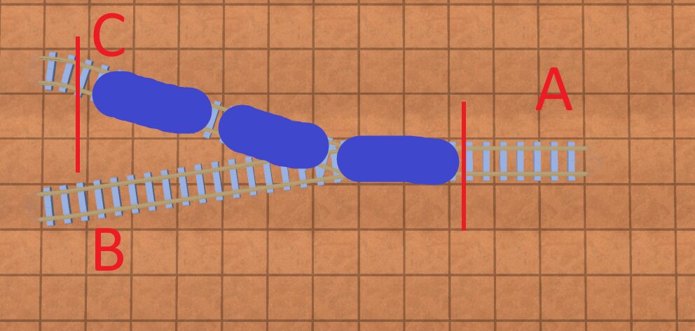
Version 7: Reversing at Junctions
Take this path:
Imagine we want to go from C to B. We can see clearly that from C, we would have a train go to A, reverse, and then go to B. However, our pathfinding algorithm(as it stands now) would not allow that; the only way we can “reverse” is if there’s an explicit stop placed into the graph.
So how do we fix this?
Well put on your PM hat again for a second. An “easy” solution would be for the user to just help the pathfinding algorithm by adding a stop to the schedule somewhere near A once the train’s fully reversed. Then the pathfinding algorithm works. Depending on how (un)intelligent you want your pathfinding algorithm to be, that could be good enough.
But for the sake of argument, let’s say we want to model this so the pathfinding algorithm is fully autonomous to do this on its own.
The solution is simple, but elegant: allow reversing at all junctions. This is the only other place(besides stops) where it makes logical sense for a train to reverse; it’s not going to reverse in the middle of a track for no reason; it’s only going to reverse at a junction if it wants to go back onto a track that’s facing the same way as the track it was just on.
To do this, we will simply add an edge that loops back on a junction for each track, with the cost being the length of the train(since that’s how far on the track it’ll need to back up to do the reversal). In order to reverse on a track, the track has to be long enough to hold the whole train. If it’s not long enough, the train can’t reverse. Also note: junction reversal edges are train length-dependent, so you have to add and remove them at runtime for each train when calculating its path. This can have implications for how you implement your graph algorithm and the runtime of things. For example, if you want to pathfind for n trains of different lengths, for each train, you’ll have to 1) add the train’s reversal edges to the graph 2) pathfind 3) remove the reversal edges for that train 4) do it for the next train.
The below image has reversal edges added for each track. Ignore the box with the word “nodes” in it for now:
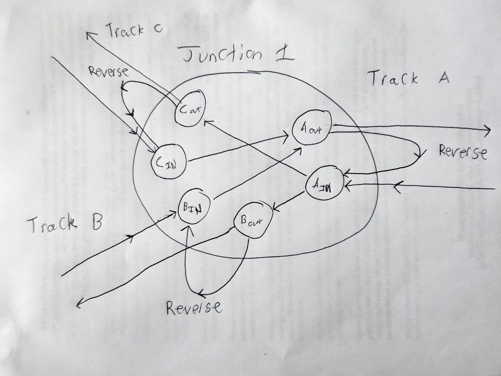
As you can see in the image above, Aout is connected to Ain via a reverse edge; Cout to Cin; and Bout to Bin.
Modeling a reversal edge
The only data we need for a reversal edge is the cost of the reversal: that would be the length of the train, since the train will have to back up fully through the junction before it can reverse. Since most pathfinding algorithms already require a cost associated with an edge, there’s no extra data encoded here. This cost can also be used to determine how far on the track past the junction the train needs to go in order to reverse, and that can be used to construct the path of the train.
So your code for your Edge class would look like this:
class Edge
	var cost: float # The cost from the start node to the end node(train length if reversal edge); otherwise just the length of the track

	# Optional train if this is a reversal edge and it’s not known at runtime
	var train: Train = null
Reversing across multiple junctions
Okay, but what if you had this setup?
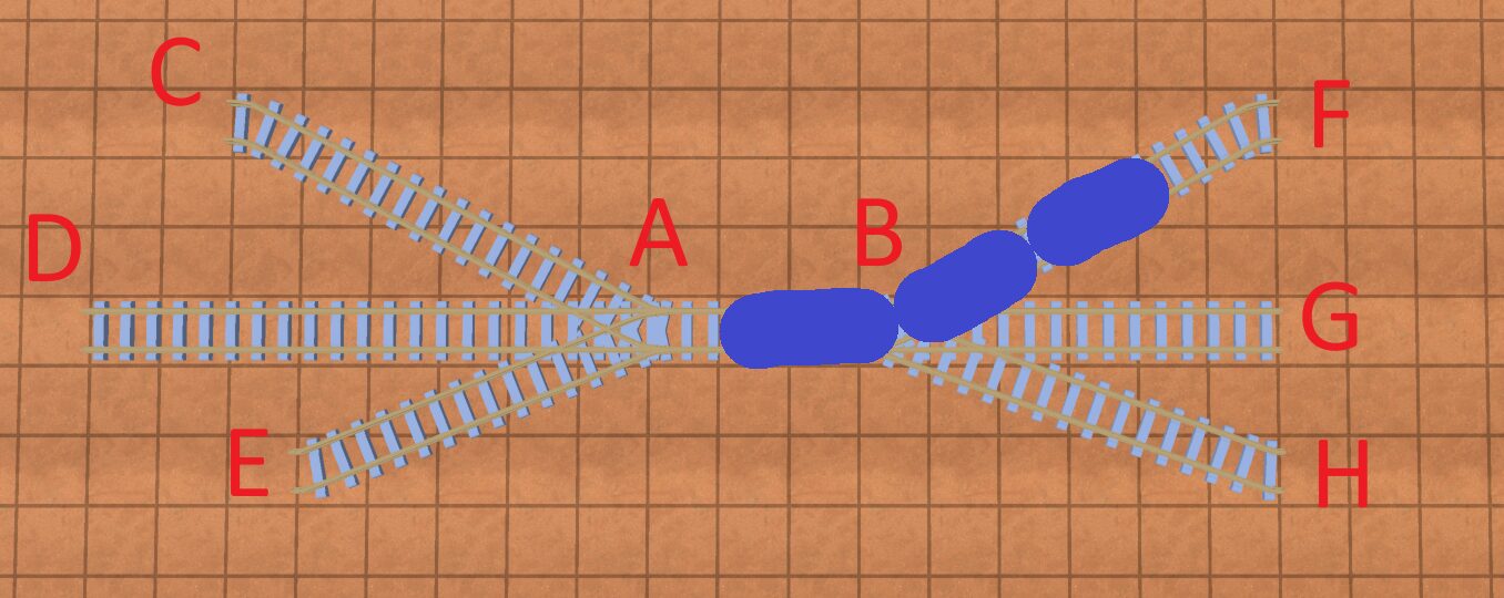
Say you have a 3-car train pictured above, and you wanted to go from point F to point H? To do this, you would need to cross junction A and then pick a point C, D, or E to fully “back up” to before you can go across junction B to point H.
This can get complicated. Once again, you can put on your PM hat: “do I actually need this?” If you don’t care for your pathfinding algorithm to reverse across junctions, you can just check in the code if there’s enough track past a junction to back up on(before hitting another junction), and if so add the edge; if not, no edge.
But again, for the sake of argument, let’s say that’s not good enough.
In order to model this, you’d want to add an edge at every junction for every possible reverse path; so for junction B for example, for one side you could reverse along BF, BG, BH. For the other side, you might reverse across BAC, BAD, and BAE.
It can get even more complicated. Imagine you had this:
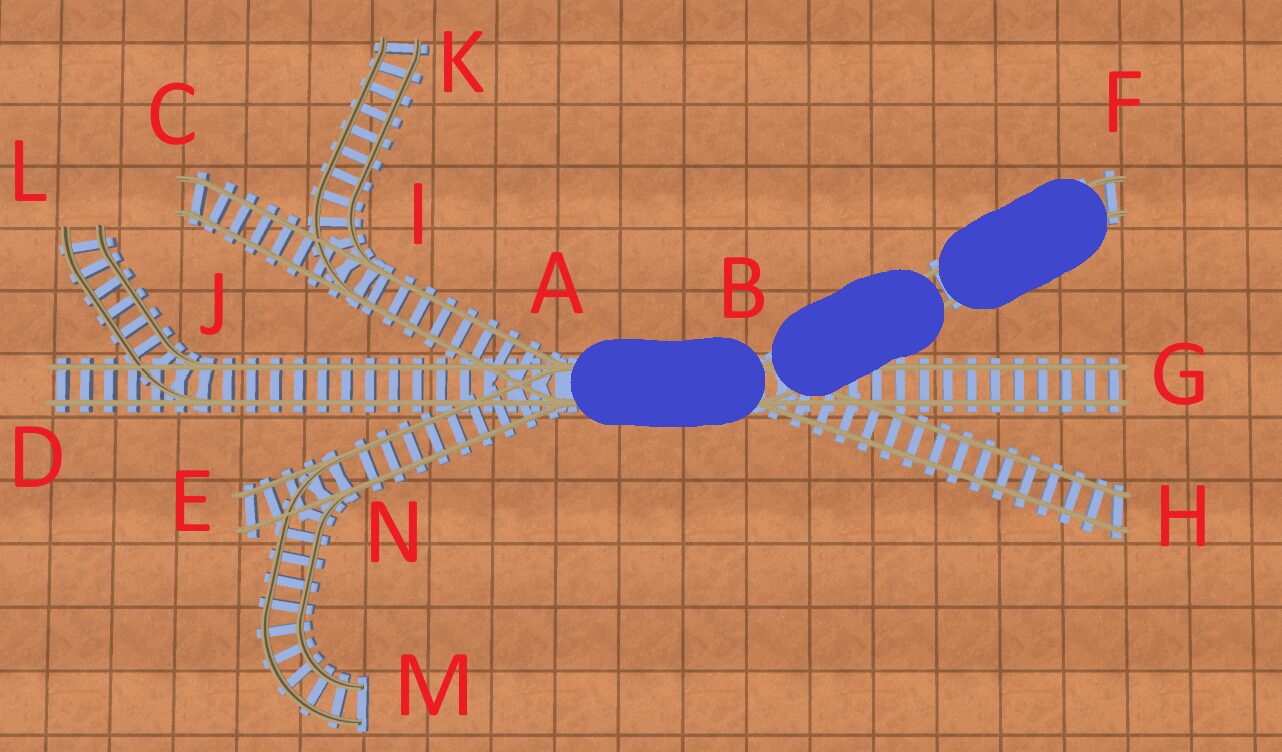
Now, if you want to go from point F to point H, you’ll have to cross at least 2 junctions: Junction A and either junction I, J, or N.
You get the point.
So what does the code/algorithm for this look like? Well, for every track connection at every junction, you want to add all possible reversal edges that start with that track. You do this by iterating “away” from the junction on that track using BFS(breadth first search) or DFS, and finding every possible combination of tracks and nodes up to the length of the train.
So in the above example, when adding reversal edges for node B, you’d have these paths:
BF
BG
BH
BAIK
BAIC
BAJL
BAJD
BANE
BANM
To run your pathfinding algorithm, you don’t actually need the nodes you traverse during a reversal; you just need the total length. When you go to construct the path however, you need to know which nodes the train will reverse over. To do this, simply add some data to your “reversal” edge that records all the nodes the train traversed over when reversing.
It’d look like this:
class Edge
	var cost: float # The cost from the start node to the end node

	# Optional train if this is a reversal edge and it’s not known at runtime
	var train: Train = null

	# Optional path if there are a couple of nodes to get to this node; this will
	var intermediate_nodes: Array[Node] = []
	var intermediate_nodes_train: Train = null # What train this edge is for
Notes on the code
A few changes to the code presented above that are different to my implementation
- In my code I changed StopNode and JunctionNode to inherit from Node, and pulled out the common elements on both. This allowed me to use the the “Node” type in my Graph structure
- I added a “Track” class below; I don’t believe it is necessary to understand the Track class but the reader might find it useful for their own implementation
Conclusion
Wow, so that wasn’t as easy as a graph with nodes and edges.
If you have thoughts on how to make this easier, or have implemented train tracks in your game and took a different approach, I’d love to hear your thoughts in the comments below. Thanks for reading and hopefully you found this useful!
Code Appendix:
If you just want the completed data models, or want to reference them, here they are below:
class Junction:
	var _angle: float
	var _opposite_angle: float
	var lines: Array[TrackConnection]

class TrackConnection:
	var track: Track
	var approach_from_angle: bool

class Edge
	var cost: float # The cost from the start node to the end node

	# Optional train if this is a reversal edge and it’s not known at runtime
	var train: Train = null

	# Optional path if there are a couple of nodes to get to this node; this will
	var intermediate_nodes: Array[Node] = []
	var intermediate_nodes_train: Train = null # What train this edge is for

class StopNode extends Node
	var track_pos: float # position along the track from the front of the track
	var train: Train # The train this stop is for

class JunctionNode extends Node
	var junction: Junction
	var connected_at_start_of_track: bool # Whether the start of the end of the track is connected to this junction
	var is_out_node: bool # Whether this node is an “in” or an “out” node

class Node
	var name: String
	var track: Track

class Track:
	var start_junction: Junction
	var end_junction: Junction
	var length: float
	# This can contain an array of points, or a formula for a curve(or series of lines/curves) to determine where a train actually is on a track. In my case, I used DubinsPath which you can see my implementation here: https://github.com/Kevin-Jonaitis/dubinspath
	var path: Path